

Pneumatic Valve Actuators for Industrial Flow Control
- Valve
- Oct 23, 2026
- 3 Views
Pneumatic Valve Actuators for Industrial Flow Control
Industrial automation relies on reliable equipment to control the movement of liquids, gases, steam, and other process media. Valves play a major role in regulating flow, but operating them manually can become difficult in large facilities or demanding industrial environments. Automated valve systems provide a practical solution by improving control, consistency, and operational efficiency. Among the available automation technologies, pneumatic systems are widely used because of their simple construction, rapid response, and dependable performance.
Pneumatic Valve Actuators use compressed air to generate mechanical movement that opens, closes, or positions a valve. They are commonly installed in manufacturing plants, chemical processing facilities, water treatment systems, power stations, and oil and gas operations. Their ability to perform repeated movements makes them suitable for applications that require frequent valve operation. When correctly selected and maintained, these actuators can support safe processes, reduce manual intervention, and improve the overall productivity of industrial equipment.
What Are Pneumatic Valve Actuators?
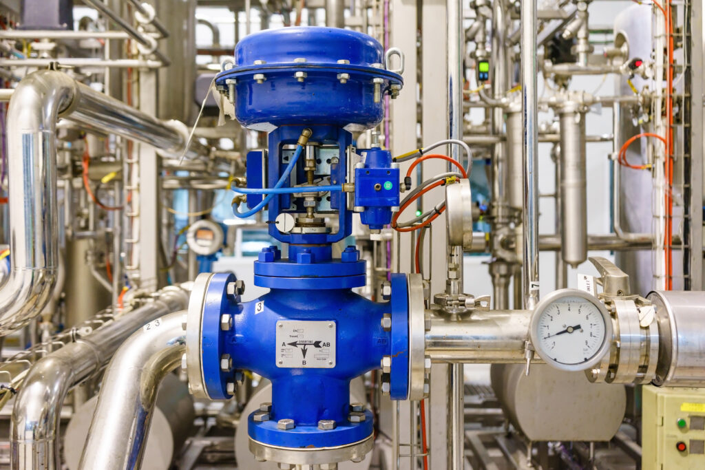
A pneumatic valve actuator is a mechanical device that converts the energy of compressed air into motion. This motion operates a connected valve, allowing the flow of a process medium to be started, stopped, or regulated. Depending on the valve design and actuator configuration, the movement may be linear or rotary. Linear motion is generally associated with valves such as globe valves, while rotary motion is commonly used with ball valves, butterfly valves, and plug valves.
The actuator is usually connected to a compressed air supply and may operate through a control signal from a pneumatic controller, solenoid valve, or automated control system. When air enters the actuator chamber, pressure acts on a piston or diaphragm, producing movement. This movement is transferred to the valve stem or shaft. The required air pressure, actuator size, and operating mechanism depend on the valve torque or thrust requirements, process conditions, and intended operating frequency.
How Do Pneumatic Valve Actuators Work?
The operating principle is based on the relationship between compressed air pressure and mechanical force. When the control system sends an operating command, a directional control valve allows compressed air to enter the appropriate actuator chamber. The air pressure moves an internal piston, diaphragm, or vane, depending on the actuator design. The resulting movement rotates or pushes the valve mechanism into the required position.
In a double-acting actuator, compressed air is supplied alternately to opposite sides of the piston to produce opening and closing movements. In a spring-return actuator, compressed air moves the mechanism in one direction while a spring provides the return force when air pressure is removed. This configuration can help achieve a predetermined valve position during certain supply failures, provided the system has been designed for that purpose. Positioners, limit switches, and feedback devices can also be added to improve control accuracy and communicate valve status to operators.
Main Types of Pneumatic Valve Actuators
Different actuator designs are available to meet the requirements of industrial valves, operating pressures, and automation systems. The correct choice depends on the type of movement required, the force or torque needed, the available compressed air supply, and the preferred response during a failure. Some designs are suitable for simple opening and closing operations, while others are intended for more demanding control applications.
The major categories include spring-return actuators, double-acting actuators, rack-and-pinion rotary actuators, scotch-yoke actuators, piston actuators, and diaphragm actuators. Although some categories overlap, each describes a different aspect of the actuator's operating mechanism. Understanding these differences helps engineers, maintenance professionals, and equipment buyers select a configuration that matches the valve and process requirements.
1. Spring-Return Actuators
Spring-return actuators use compressed air to move the actuator in one direction and an internal spring to produce the return movement. When air pressure is removed, the spring moves the mechanism toward its designed default position. This arrangement is particularly useful for applications where a valve must move to a specified position following a loss of instrument air.
Depending on the valve configuration, the spring can be arranged to close or open the valve. This is often described as fail-close or fail-open operation. Spring-return designs are frequently selected for emergency isolation, process protection, and automated shutdown systems. However, the complete assembly must be evaluated to confirm that it achieves the required safe position under actual operating conditions.
2. Double-Acting Actuators
Double-acting actuators use compressed air to power movement in both directions. Air is directed to one chamber to operate the valve in one direction and to the opposite chamber to reverse the movement. Since a return spring is not required for the basic operating cycle, these designs can provide substantial output torque within a compact package.
They are widely used in industrial automation systems that require repeated opening and closing operations. Double-acting configurations are suitable for ball valves, butterfly valves, plug valves, and certain linear control valves. Their performance depends on air pressure, available airflow, valve resistance, and actuator sizing. If the air supply fails, the final valve position is not automatically guaranteed, so additional components may be required where a defined failure response is necessary.
3. Rack-and-Pinion Actuators
Rack-and-pinion actuators are rotary devices that convert the linear movement of internal pistons into rotational movement through a rack and pinion gear mechanism. Compressed air pushes the pistons, moving the racks and rotating the central output shaft. This shaft connects to the valve stem and provides the turning force needed to operate the valve.
These actuators are commonly used with quarter-turn valves, including ball and butterfly valves. Their compact construction, relatively straightforward installation, and fast response make them suitable for automated production lines and process control systems. They are available in several sizes and configurations, allowing users to select an appropriate model based on required torque, operating pressure, and mounting arrangements.
4. Scotch-Yoke Actuators
Scotch-yoke actuators use a mechanical linkage that converts linear piston movement into rotary motion. The mechanism produces a changing torque output through the operating stroke, which can be advantageous for valves with higher breakaway torque requirements. These actuators are often considered for demanding industrial applications involving larger valves or challenging process conditions.
Their robust construction can support heavy-duty service when correctly specified. They are commonly used in oil and gas facilities, pipelines, power generation plants, and industrial process installations. Selection should account for the valve's torque requirements throughout the full stroke, the operating pressure range, the expected number of cycles, and the environmental conditions surrounding the equipment.
5. Piston and Diaphragm Actuators
Piston actuators use compressed air acting on a piston inside a cylinder to generate force. They are suitable for applications that require substantial thrust or rotary torque, depending on the connected mechanism. Their performance depends on piston area, pressure, friction, and the resistance created by the valve or process.
Diaphragm actuators use a flexible membrane to convert air pressure into mechanical movement. They are commonly associated with linear control valves, where the actuator moves a valve stem to regulate flow. Spring-loaded diaphragm designs can provide a defined return direction when air pressure is lost. The choice between piston and diaphragm designs depends on the required travel, force, control characteristics, available space, and maintenance requirements.
Key Components of a Pneumatic Actuation System
A complete actuation system includes more than the actuator housing itself. Several components work together to supply air, direct movement, and communicate valve position to the control system. Their compatibility and correct installation are important for reliable operation.
The principal components generally include:
Actuator housing: Contains the internal operating mechanism and withstands the intended operating conditions.
Piston or diaphragm: Converts air pressure into mechanical force.
Spring mechanism: Provides return movement in spring-return configurations.
Directional control solenoid valve: Directs compressed air to the appropriate chamber.
Air filter and regulator: Help maintain suitable air cleanliness and supply pressure.
Positioner: Controls valve travel according to the desired position in modulating applications.
Limit switches: Indicate whether the valve has reached designated travel positions.
Mounting bracket and coupling: Connect the actuator securely to the valve.
Proper coordination between these components helps maintain consistent valve movement, improve monitoring, and reduce operational interruptions.
Advantages of Pneumatic Valve Actuators
Pneumatic Valve Actuators are widely used because compressed air can provide a practical source of energy for repetitive industrial operations. Their simple operating principle and availability in different configurations make them suitable for numerous valve automation requirements. When properly sized and integrated, they can improve process consistency while reducing the need for manual valve operation.
Some important advantages include:
Fast operation: Supports quick opening and closing cycles in many applications.
Reliable construction: Many designs have relatively few moving parts.
Automation compatibility: Can be integrated with solenoid valves, PLCs, and distributed control systems.
Flexible configurations: Available for rotary and linear valve movement.
Suitable for demanding environments: Properly selected units can operate in challenging industrial conditions.
Potential fail-safe operation: Spring-return designs can move valves to a specified position when air pressure is lost.
Reduced manual effort: Enables remote operation in locations that are difficult or unsafe to access.
Despite these benefits, compressed air generation and treatment require energy and maintenance. Air leaks, insufficient pressure, moisture, and contamination can affect performance. Therefore, the complete pneumatic system should be considered when evaluating operating costs and reliability.
Industrial Applications of Pneumatic Valve Actuators
Pneumatic Valve Actuators are used in industries where dependable valve automation, quick response, and repeatable operation are important. They can be integrated into basic on-off systems as well as more advanced process control arrangements. The appropriate actuator design depends on the valve type, process medium, operating conditions, and required control function.
Common industrial applications include:
Oil and Gas Industry
Oil and gas facilities use automated valves to manage the movement of crude oil, natural gas, and other process fluids. Pneumatic actuators can operate isolation valves, pipeline valves, and emergency shutdown valves. In these installations, engineers must consider pressure requirements, environmental exposure, corrosion protection, and the necessary response during an air supply failure.
Chemical and Petrochemical Processing
Chemical plants require dependable control of liquids, gases, and chemical mixtures throughout production processes. Pneumatic actuation can support automated dosing, isolation, and flow regulation. The actuator housing, seals, and associated accessories should be suitable for the surrounding environment and any applicable hazardous-area requirements.
Water and Wastewater Treatment
Water treatment facilities use automated valves to manage distribution, filtration, backwashing, and wastewater processing. Pneumatic actuators can operate butterfly valves, ball valves, and other compatible valve types. Correct material selection and protection against moisture and corrosion are particularly important in these environments.
Power Generation and Manufacturing
Power plants and manufacturing facilities use actuators to support cooling water systems, steam-related processes, production lines, and utility distribution. In automated factories, fast and repeatable valve operation can help maintain production schedules and improve process consistency.
Comparison of Pneumatic Actuator Types
The following table summarizes the major actuator configurations and their common uses.
Actuator type | Operating principle | Typical application | Main consideration |
|---|---|---|---|
Spring-return | Air-powered movement with spring return | Emergency isolation valves | Spring torque and fail position |
Double-acting | Air powers both directions | Automated process valves | Reliable air supply |
Rack-and-pinion | Linear piston movement creates rotation | Ball and butterfly valves | Required output torque |
Scotch-yoke | Linkage converts linear motion into rotation | Heavy-duty rotary valves | Torque requirements throughout travel |
Piston | Air pressure acts on a piston | High-force applications | Pressure and piston sizing |
Diaphragm | Air pressure moves a flexible diaphragm | Linear control valves | Travel and thrust requirements |
How to Select the Right Pneumatic Actuator
Choosing the right actuator involves evaluating the complete valve assembly rather than selecting a product based on size or price alone. An undersized actuator may struggle to operate the valve, while an unnecessarily large unit can increase purchase costs and compressed air consumption.
Consider the following factors before making a selection:
Valve type and movement: Determine whether the valve requires linear movement or quarter-turn rotation.
Required torque or thrust: Evaluate the valve manufacturer's operating requirements, including breakaway torque and seating loads.
Available air pressure: Confirm that the minimum expected supply pressure provides sufficient operating force.
Operating frequency: Consider the number of cycles and the expected service life.
Failure response: Establish whether the valve must fail open, fail closed, or follow another defined response.
Control requirements: Decide whether simple on-off operation or continuous positioning is required.
Environmental conditions: Evaluate temperature, humidity, dust, vibration, and potential corrosive exposure.
Maintenance accessibility: Choose a design that can be inspected and serviced conveniently.
These factors should be reviewed together to ensure that the selected equipment meets the application's technical and operational requirements.
Maintenance Tips for Long-Term Performance
Regular maintenance helps prevent unexpected shutdowns and keeps pneumatic equipment operating consistently. Although many actuator designs are relatively simple, seals, springs, bearings, gears, and air control components can wear over time. A preventive maintenance schedule should reflect the operating environment, duty cycle, and manufacturer's recommendations.
Important maintenance practices include:
Inspect compressed air lines, fittings, and connections for leakage.
Check the air filter and regulator for contamination or incorrect pressure settings.
Examine seals and external components for visible wear or damage.
Verify that the valve completes its full opening and closing stroke.
Test limit switches and position feedback devices.
Check mounting bolts, couplings, and mechanical connections.
Inspect the solenoid valve and control signals for correct operation.
Test the specified failure response according to approved safety procedures.
Keep maintenance records to identify recurring problems and performance changes.
Before carrying out maintenance, isolate the equipment, depressurize the system, and follow the required lockout and safety procedures. Spring-return actuators may contain stored mechanical energy, so disassembly should only be performed by trained personnel following the manufacturer's instructions.
Common Challenges and Their Solutions
Even well-designed pneumatic systems can experience operational problems when the air supply, actuator sizing, or control components are unsuitable. Identifying the cause of a problem early can help reduce downtime and avoid unnecessary component replacement.
Slow valve movement: This may result from low air pressure, restricted tubing, undersized control valves, or excessive mechanical resistance. Inspect the air supply and verify that the control components provide adequate flow.
Incomplete valve travel: Insufficient actuator output, incorrect travel stops, mechanical interference, or a sticking valve may prevent full movement. Check the valve torque requirements and inspect the complete assembly.
Air leakage: Worn seals, damaged tubing, loose fittings, or deteriorated connections can reduce operating efficiency. Identify the leakage source and replace damaged components as necessary.
Unreliable positioning: Incorrect positioner settings, faulty feedback devices, or unstable air pressure may cause inconsistent control. Check calibration, signal integrity, and the air supply.
Addressing these issues systematically helps improve reliability and extends the service life of the equipment.
Conclusion
Pneumatic Valve Actuators provide a practical and dependable solution for automating industrial valves across manufacturing, chemical processing, oil and gas, water treatment, and power generation. By converting compressed air into mechanical movement, they support efficient valve operation, remote control, and integration with modern automation systems.
Understanding actuator types, operating principles, component functions, and application requirements is essential when selecting the right configuration. Factors such as valve torque, air pressure, operating frequency, environmental conditions, and the required failure response should always be considered. Combined with proper installation and preventive maintenance, a correctly selected pneumatic actuator system can improve process reliability, reduce manual intervention, and support consistent industrial performance over the long term.
Related Posts
- Oct 14, 2026
- SUDE
- 10